Data for the fatigue strength calculation:
- Geometry data of the relevant components.

- Load situation as a progression over time (for example, forces, moments, displacements, accelerations).
- Material data and safety factors in the form of e.g. SN curves.

Procedure for fatigue strength calculation with our internal tool:
- Modelling and calculation of an FE model with unit load cases.

- Determination of the multiaxial stress state over time by scaling the unit loads from the FE model with the provided time series of the load.
- Preparation of the time series.
- Calculation of the damage by counting the stress load changes (principal stress difference or critical plane approach) and verification with the material data and safety factors.
 Figure 1: excerpt of the source code
Providing the results:
- The results are graphically presented (for example, by plots of the service life). In this way, possible critical points of the structure can be identified.
- Proposed changes are discussed based on many years of experience in fatigue strength calculation and numerical simulation if the required service life is not being fulfilled.
- Either a short presentation or an auditable report is handed over.
Procedure of a numerically supported buckling verification using the example of a tower of a wind turbine:
- Modelling of the tower section as a shell model.
- Carry out linear and non-linear pre-calculations.
- Consideration of different suitable imperfection shapes to determine the governing imperfection shape (use of imperfection shapes with affinity to the eigenshape and quasi-collapse affinity; see Figure 1 and Figure 2).
- Carrying out several geometrical and material non-linear calculations with imperfections included (GMNIA).
- Determination of the load-displacement curves for each imperfection shape to determine the minimum design buckling resistance (see figure 3).
 Figure 1: eigenform affine imperfection shape
 Figure 2: quasi-collapse imperfection shape
 Figure 3: load displacement curves for the buckling verification
In the offshore sector, one type of connection between pile and sleeve is the grout connection. Two pipes are overlapped and the space in between is filled with grout. Shear keys are added to prevent sliding through.
To calculate this connection, we use material laws such as the Drucker Prager or Menetrey Willam material law. The uniaxial compressive strength Rc, uniaxial tensile strength Rt and biaxial compressive strength Rb are used for the two material laws. With these material laws, the concrete properties are well modeled. The assessment is carried out according to the Model Code for Concrete Structures 2010.
In this example, a grout connection was simulated on a small model scale. It can be clearly seen that the compression struts are formed in the concrete and there is an increased load locally at the shear keys (see figure 1).
 Figure 1: Schematic visualisation of a grout connection (right) with results (left)
Some tasks require customised calculations. For such tasks, we develop calculation tools in-house. With these we can:
- carry out analytical verifications of wind turbine towers with the support of a program.
- Carry out verifications efficiently and quickly.
- Identify optimisation potential in a targeted manner.
In the process
- the verifications are carried out according to common standards and guidelines (for example Eurocode 3, IEC guidelines, DIBt guideline).
- customer-specific requirements are included.
- Updates to the relevant standards and directives are taken into account.
The results are output
- in diagrams.
- as a detailed solution with intermediate results.
 Figure 1: excerpt of the source code (left) and the result output of the modal analysis (right)
Various components on the drive train of a wind turbine must be verified:
- Verification of the bearing hosuing
- Verification of the generator carrier
- Verification of the machine carrier
- Verification of the drive shaft
For the verification, an FE model is created from the CAD models of the relevant components and the relevant regions are finely meshed (see Figure 1). Furthermore, the force distribution from the rotor hub to the tower head flange is modelled (see figure 2). The bearing of the drive shaft is taken into account. For example, the following verifications are carried out:
- ultimate load verification
- fatigue load verification
The fatigue verification can be carried out with our internal calculation tool and the time series provided.
 Figure 1: FE model of a drive train
 Figure 2: deformation of a drive train
An example of a dynamic FEM calculation is a response spectrum analysis. The calculation aims to determine good approximations for the maximum stresses in a structure with relatively little effort. In this process, the results from a modal analysis are used together with a known excitation spectrum to calculate the stresses and deformations of a structure (see figure 1). With a response spectrum analysis, engine and body attachments, for example, can be evaluated in terms of fatigue strength.
 Figure 1: profile of an excitation spectrum
In the offshore sector, we have gained extensive experience in the following sectors:
- Verifications of jackets (s. figure 1)
- Verifications of monopiles
- Verifications of tripiles (s. figure 2)
- Verifications of grout connections (s. figure 3)
- Verifications of suction buckets
- Verifications of movable jack up rigs (s. figure 4)
For the calculation of offshore structures, among other things, wave loads are taken into account. These are applied to the model from different directions in a quasi-static FEM calculation. For the definition of the wave loads, external influences such as water depth, marine vegetation and the scouring of the seabed at the connection are taken into account.
 Figure 1: FE model of a Jackets
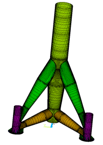 Figure 2: FE modell of a Tripiles
 Figure 3: FE model of a grout connection
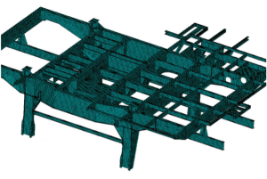 Figure 4: FE model of the upper substructure of a movable jack up rig
We have gained extensive experience in shipbuilding. This includes FEM calculations of:
- Details on cruise ships
- Hull sections
- Window cut-outs
- Signal towers
- Bridge and deck houses on container ships
FEM calculation in the field of shipbuilding using the example of strength calculations for the crane columns of a heavy lift vessel. In addition to the crane columns, strength verifications were carried out on sections in the transverse plates between two decks (see figure 1).
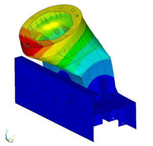 Figure 1: Deformation of the crane column
If damage occurs during operation (e.g. due to rotor blade impact or impact loads) or if construction deviations occur during production, a subsequent assessment of the components can imply that the affected components can continue to be used. Due to our extensive experience in this sector, we are able to
- model e.g. existing dents in the component on the basis of individual measuring points (see figure 1).
- model global or local dents in the component using global or local point clouds, for example.
- model construction deviations or implement them in existing models.
In the case of damage or a building deviation, for example, the following verifications must be carried out again:
- Fatigue load verification
- Stability verification
- Ultimate load verification
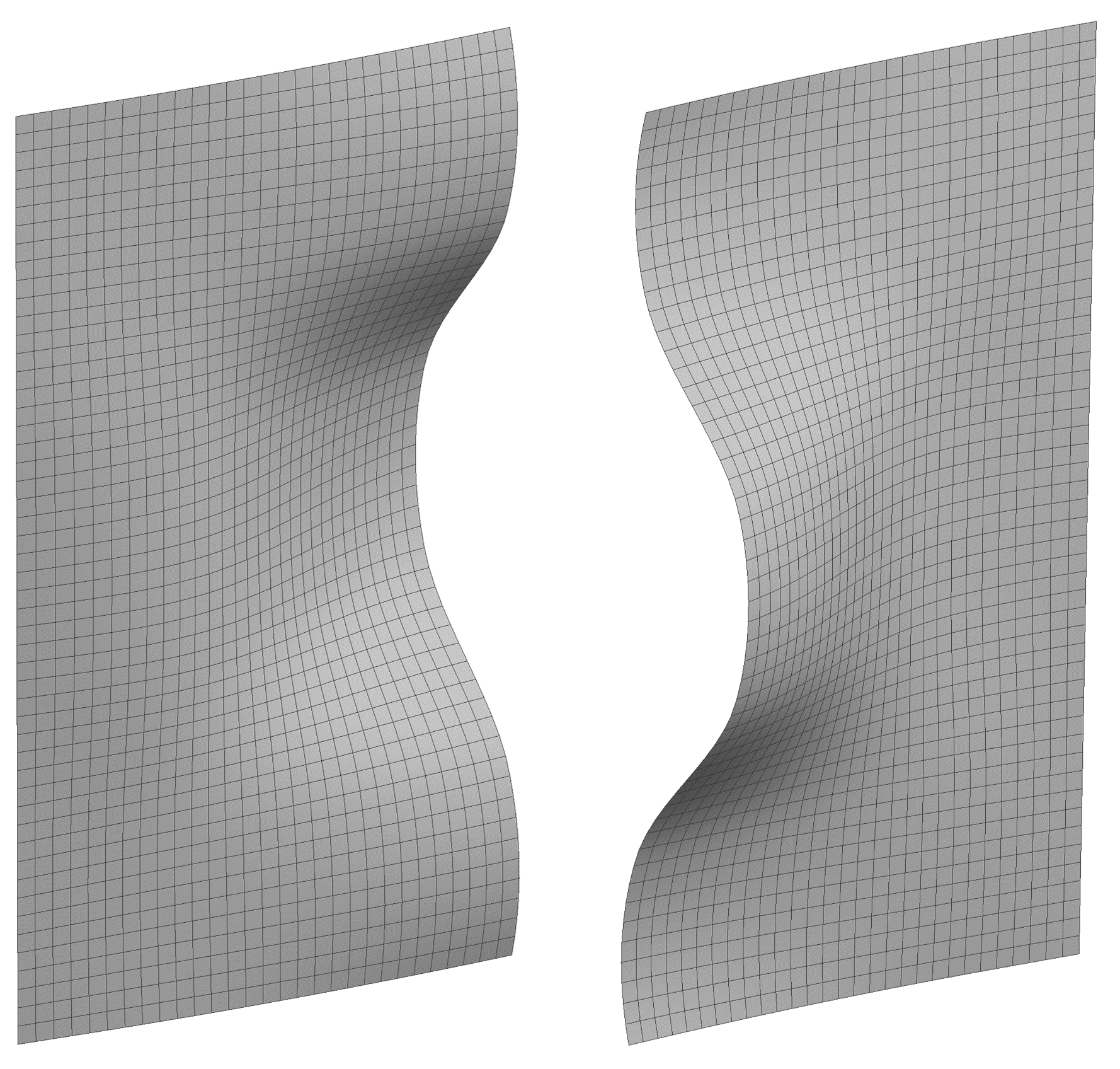 Figure 1: local dent modelled on the basis of individual measuring points in two views (sectional view).